
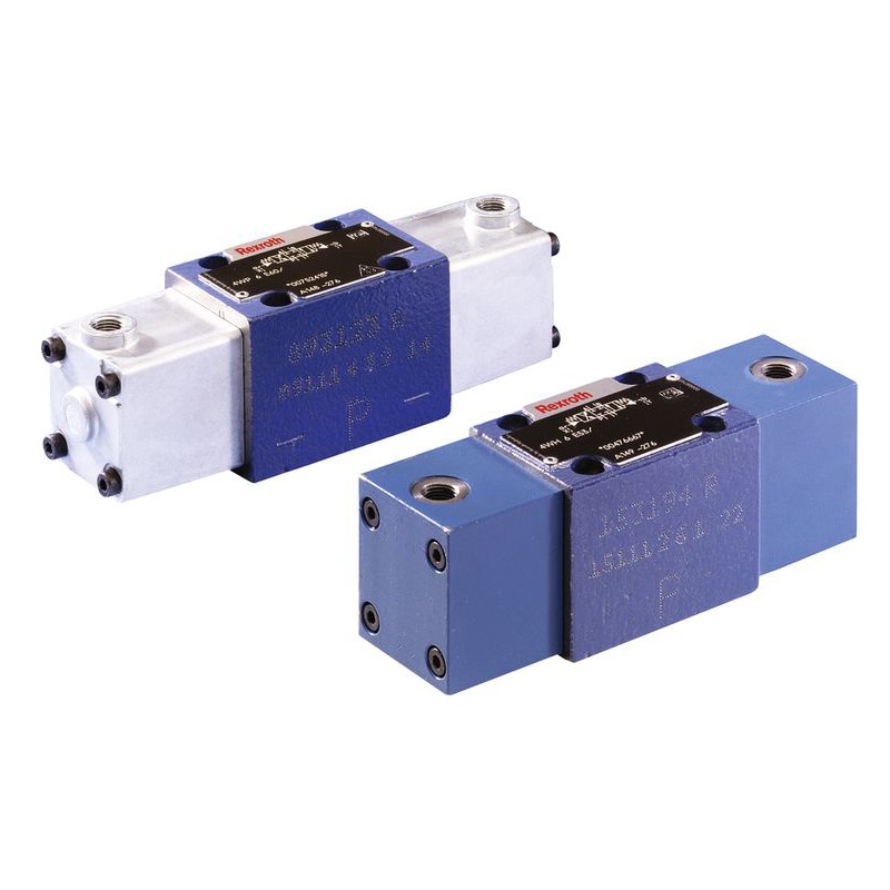
Bosch Rexroth Directional Spool Valves 4WE10 3WE10
in stock
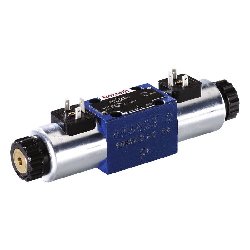
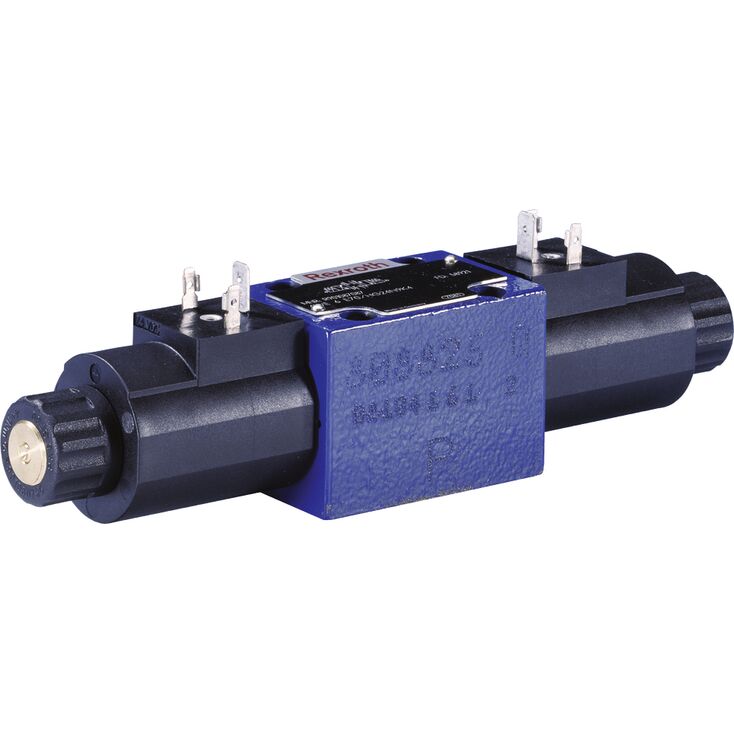
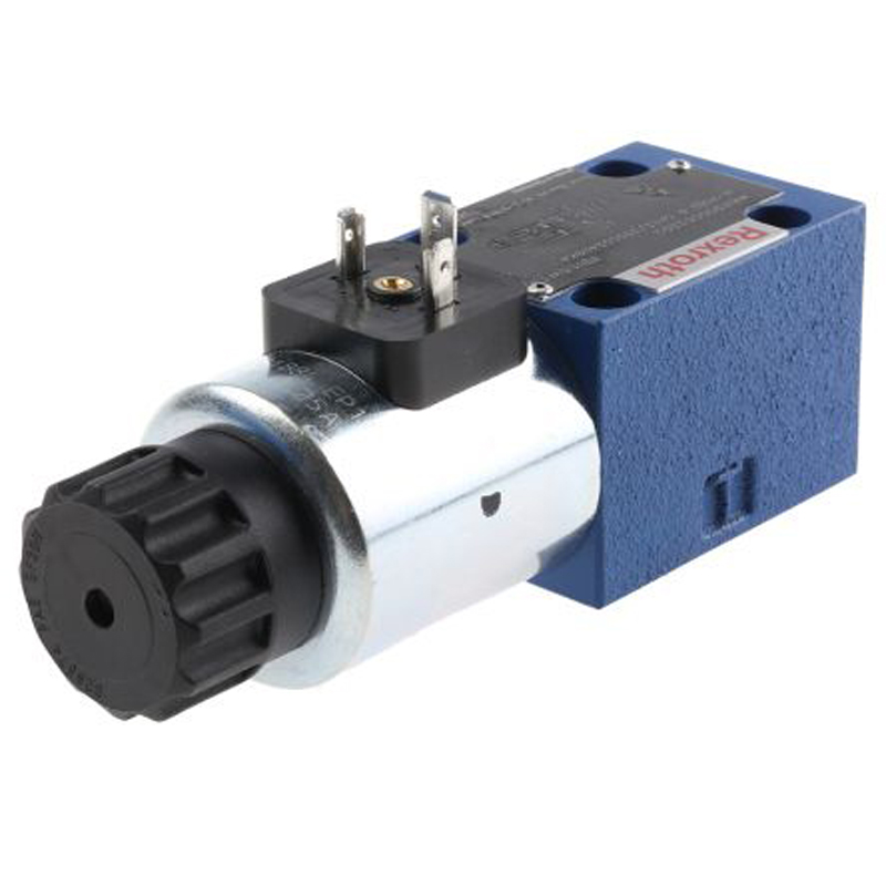
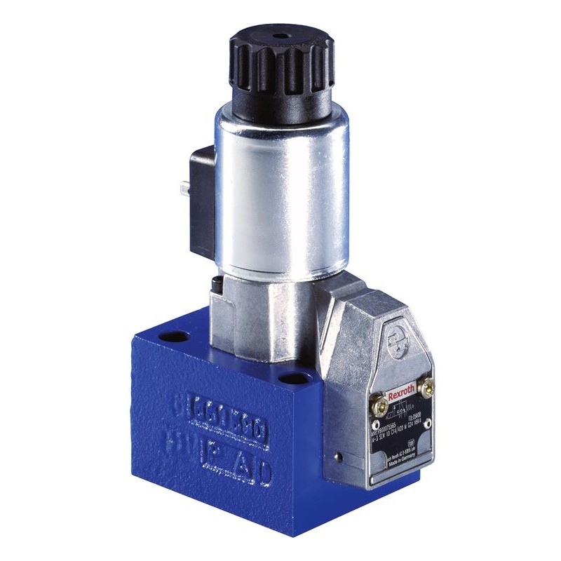
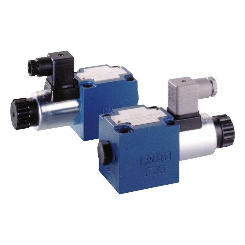
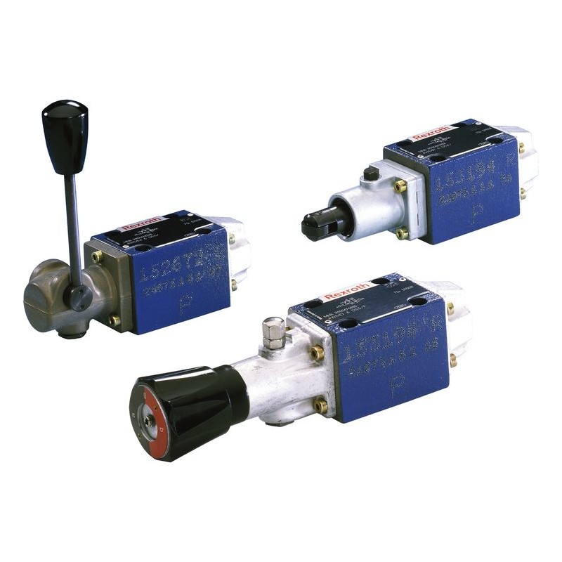
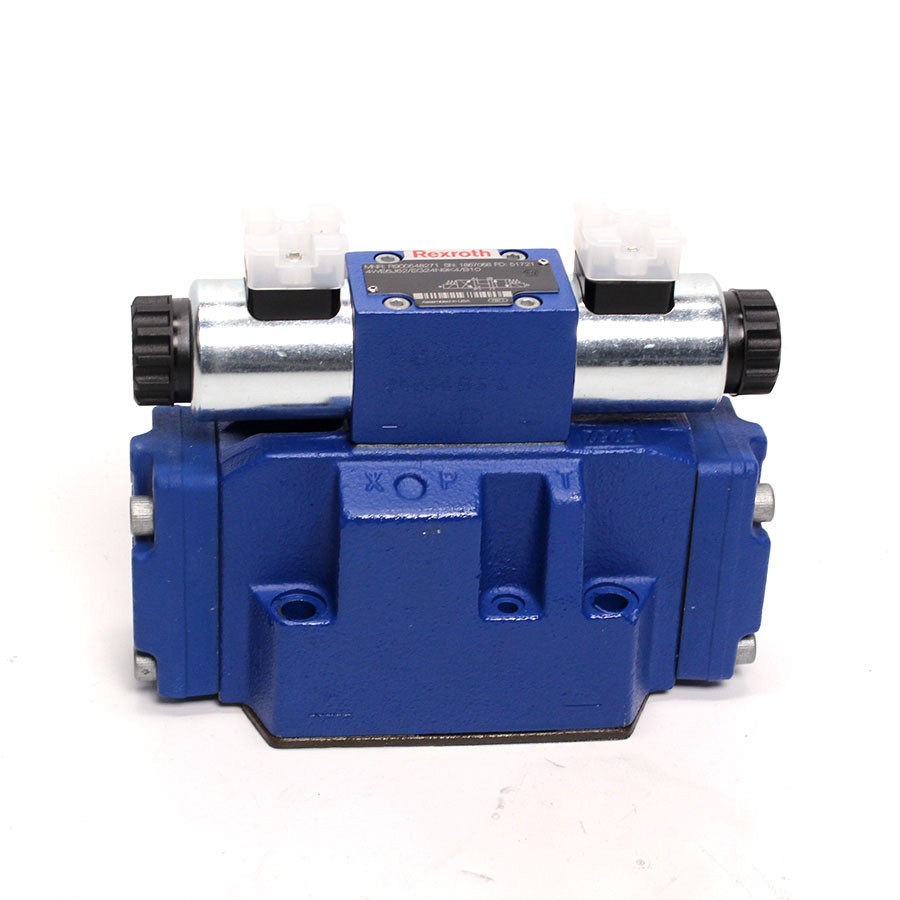
Type WE direct operated directional spool valves with solenoid actuation 4/3-, 4/2- or 3/2-way versions
Size 10
Component series 5X
Maximum operating pressure 350 bar
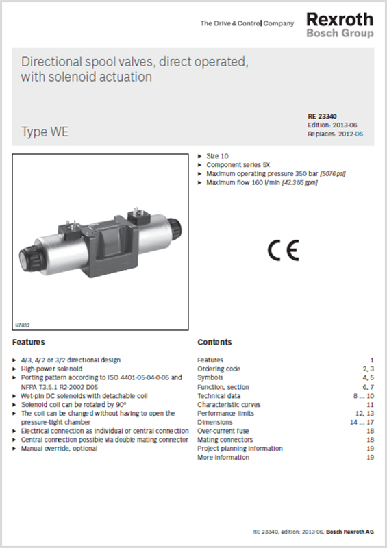
Bosch Rexroth Directional Spool Valves Direct Operated with Solenoid Actuation Type WE
- Size 10
- Component series 5X
- Maximum operating pressure 350 bar [5076 psi]
- Maximum flow 160 l/min [42.3 US gpm]
- NBR seals
Features:
- 4/3-, 4/2- or 3/2-way version
- Porting pattern according to ISO 4401-05-04-0-05 and NFPA T3.5.1 R2-2002 D05
- High-power solenoid, optionally rotatable by 90°
- Electrical connection as individual or central connection
- Cartridge optionally equipped with PWM connector (fast switching amplifier, energy reduction)
- Manual override, optional
- CE conformity according to the Low Voltage Directive 2006/95/EC for electrical voltages >50 VAC or > 75 VDC
- Solenoid coil with UR approval UL 429
- Approval according to CSA C22.2 No. 139-10, optional
Domestic and export sales enquiries are welcome from end users, original equipment machinery manufacturers and trade suppliers from all industrial sectors.
If you can't find what you are looking for, need product pricing, delivery, technical support or associated services CONTACT GOKOSO or call our sales office +86 17623383975
| PART NUMBER | MATERIAL NUMBER | IN STOCK | PRICE | SHIP | ADD TO MY PARTS LIST |
|---|
01 | 02 | 03 | 04 | 05 | 06 | 07 | 08 | 09 | 10 | 11 | 12 | 13 | 14 | 15 | 16 | 17 | ||
WE | 10 | 5X | / | E | / | * |
01 | 3 main ports | 3 | ||
4 main ports | 4 | |||
02 | Directional valve | WE | ||
03 | Size 10 | 10 | ||
04 | Symbols e. g. C, E, EA, EB, etc.; for the possible version, see Symbols | z. B. C | ||
05 | Component series 50 to 59 (50 to 59: unchanged installation and connection dimensions) | 5X | ||
06 | With spring return | no code | ||
With reinforced compression spring | D | |||
Without spring return | O | |||
Without spring return with detent | OF | |||
07 | High-power solenoid, wet-pin, with detachable coil | E | ||
08 | Direct voltage 12 V | G12 | ||
Direct voltage 24 V | G24 | |||
Direct voltage 26 V | G26 | |||
Direct voltage 48 V | G48 | |||
Nominal voltage 96 V at DC solenoid in operation with AC voltage mains (AC voltage mains 100/110 V - 50/60 Hz with an admissible voltage tolerance of +/- 10 %) | G96 | |||
Direct voltage 110 V | G1101) | |||
Direct voltage 125 V | G125 | |||
Nominal voltage 180 V at DC solenoid in operation with AC voltage (AC voltage mains 200 V - 50/60 Hz with an admissible voltage tolerance of +/- 10 %) | G180 | |||
Nominal voltage 205 V at DC solenoid with operation with AC voltage mains (AC voltage mains 230 V – 50/60 Hz with an admissible voltage tolerance of +/- 10 %) | G205 | |||
Direct voltage 220 V | G220 | |||
Alternating voltage 100 V | W100R1) | |||
Alternating voltage 110 V | W110R1) | |||
Alternating voltage 120 V | W120R1) | |||
Alternating voltage 200 V | W200R1) | |||
Alternating voltage 230 V | W230R1) | |||
Connection to AC voltage mains via control with rectifier (see table Mating connectors) 2) | ||||
Electrical connections and available voltages see Technical data | ||||
09 | Without manual override | no code | ||
With concealed manual override (standard) | N93) | |||
With concealed manual override and protective cap 5) | N83) | |||
With lockable manual override "mushroom button" (large) | N53; 4) | |||
With manual override "mushroom button" (large), not lockable | N63) | |||
Corrosion resistance(outside) | ||||
10 | None (valve housing primed) | no code | ||
Improved corrosion protection (240 h salt spray test according to EN ISO 9227) (see also Technical data) | J3 | |||
Electrical connection | ||||
11 | Individual connection | |||
Without mating connector; connector DIN EN 175301-803 | K46) | |||
Without mating connector; connector DIN EN 175301-803 (coil with potted-in connector base and sealing element to valve housing (IP67)) | K4K6) 7) | |||
Without mating connector, 4-pole with connector M12 x 1 according to IEC 60947-5-2, integrated interference protection circuit and status LED | K72L 6) | |||
Without mating connector; connector AMP Junior-Timer | C4Z6) | |||
Central connection | ||||
Cable entry at the cover, with indicator light | DL | |||
Central plug-in connection at the cover, with indicator light (without mating connector); connector according to DIN EN 175201-804 | DK6L | |||
Without mating connector; threaded connection 1/2“-14 NPT | DAL | |||
Cable gland at the cover, with indicator light and cable bridge at the ground connection | DJL | |||
Mini-charge connector, 5-pole | DK25L | |||
For further electrical connections and available voltages, see Technical data | ||||
Switching time increase | ||||
12 | Without switching time increase | no code | ||
With switching time increase (only with symbol ".73"; not for version "D" with reinforced compression spring; more information upon request) | A12 | |||
13 | Without throttle insert | no code | ||
With throttle insert 8; 9); | ||||
Port | Throttle Ø in mm mm | |||
0,8 mm | 1,0 mm | 1,2 mm | ||
P | B08 | B10 | B12 | |
A | H08 | H10 | H12 | |
B | R08 | R10 | R12 | |
A and B | N08 | N10 | N12 | |
T 10) | X08 | X10 | X12 | |
Further throttle insert diameters upon request. | ||||
Control spool play | ||||
14 | Standard | no code | ||
Minimum (to be selected in case of reduced leakage → higher level of oil cleanliness recommended) | T06 | |||
Increased (to be selected in case of a hydraulic fluid/environment temperature difference >25 K → increased internal leakage) | T12 | |||
Seal material | ||||
15 | NBR seals | M | ||
FKM seals | V | |||
Seals for HFC hydraulic fluids | MH | |||
Low-temperature version | MT | |||
Observe compatibility of seals with hydraulic fluid used. | ||||
16 | Approval according to CSA C22.2 no. 139-10 | CSA | ||
Porting pattern according to ANSI B93.9 (if solenoid "a" is energized, channel P is connected to A) | AN | |||
17 | Further details in the plain text | * | ||
| 1) Only for “central connection” version | |
| 2) Only for “individual connection” version | |
| 3) The manual override cannot be allocated a safety function. The manual override units may only be used up to a tank pressure of 50 bar. | |
| 4) With tank pressures above 50 bar, it cannot be guaranteed that the valve remains in the position switched by the manual override "N5". | |
| 5) Protective cap must be removed prior to actuation. | |
| 6) Mating connectors, separate order, contact HYQUIP for more information | |
| 7) When the admissible valve performance limit is exceeded, throttle inserts are to be installed (see Performance limits). | |
| 8) Not with low-temperature version "MT". | |
| 9) When throttle inserts are used in channel T, the pressure in the working ports and in case of connection to the tank chambers must not exceed 210 bar. |
0ther products in the same category:
-
BACK TO NEW...
$ 70.00
-
BACK TO NEW...
$ 155.00
-
BACK TO NEW...
$ 70.00
-
BACK TO NEW...
$ 285.00
-
BACK TO NEW...
$ 334.00
-
BACK TO NEW...
$ 255.00
-
BACK TO NEW...
$ 347.00
-
BACK TO NEW...
$ 565.00
-
BACK TO NEW...
$ 382.00
-
BACK TO NEW...
$ 395.00